Seit über 25 Jahren
SIM Mini Solar Isolators

The next evolution in DC isolation
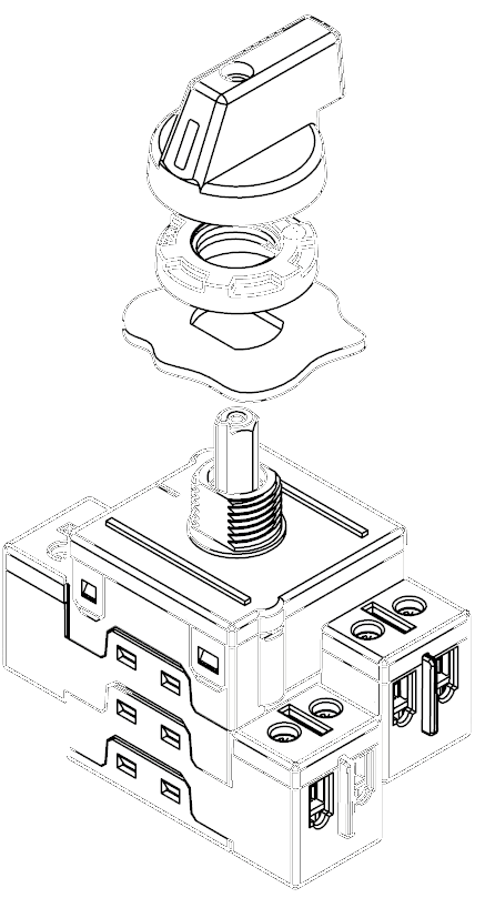
When IMO first launched its SI Series DC isolator in 2009, little did it know that the SI would soon become the safety component of choice for many of the largest solar inverter manufacturers and installers around the world. Today, with nearly 4 million installations and zero reported electrical failures, the SI Series has proved itself more than capable of handling the most demanding DC switching applications. The NEW SIM represents the next evolution in DC isolation offering all the benefits of its big brother in a compact, high reliability package. With a 35% reduction in cubic volume, reduced front plate “real-estate”, increased ratings and extended mounting options, the SIM is packed with features. Yet it retains the high reliability technology of the current SI Series including knife edge contacts, high speed operator independent switching mechanism and full arc control with guaranteed suppression time. The NEW SIM represents the next step in meeting the global demand for high reliability, compact and competitive DC safety switching solutions.
Safety as standard
In solar installations, the DC isolator is like a vehicle air-bag. It is rarely called upon but, when required, carries a huge responsibility. So it’s good to know that the IMO SI is safeguarding millions of solar installations around the world, without a single reported electrical failure. Not surprising considering the product carries all the most important approvals including UL508i. In fact the IMO SI range of solar isolators have been tested by some of the most rigorous examiners and OEM manufacturers in the world, passing with flying colours every time.
Smaller... and better
When buying IMO you can be assured of the level of quality and reliability of our products. The SIM is no exception, and just because we have managed to squeeze everything that went into our market-leading SI range into the new SIM’s compact body, we haven’t compromised on reliability. In fact, we have increased the overall ratings and extended the mounting options.

The OEM’s choice
The SI range of isolators was specifically developed for arduous DC disconnect applications and SI isolators are used by many of the largest Solar Inverter manufacturers in the world. The new SIM range features the same independent trigger ratchet switching mechanism delivering arc extinguishing times of <5ms (3ms typical). Specially designed internal arc cooling chambers control temperature rise and increase safety while knife edge contacts increase reliability and prolong electrical life. All this along with a 35% reduction in size makes the SIM Series the ideal next generation choice for OEMs globally.

Utilisation Categories
Utilisation Categories as are covered in the European Standards EN 60947-1 & EN60947-3 and define an equipment’s intended application. The list of both AC and DC categories for low-voltage switchgear and controlgear are stated in EN 60947-1 Annex A along with the relevant product standards.
Manufacturers of both switchgear and controlgear should include in their technical product data all the operational ratings for the utilisation categories for which a product is designed and as such this should remove the confusion for users and designers in their selection of the correct product.
If we consider PV installations where there are requirements for switchgear being used on the DC side then the system falls typically within two categories below (for which the relevant standard is EN 60947-3)
DC-21 Switching of resistive loads, including moderate overloads
DC-22 Switching of mixed resistive and inductive loads, including moderate overloads
DC-PV1 Switching of single PV string(s) without reverse and overcurrents
DC-PV2 Switching of several PV strings with reverse and overcurrents
Compliance to the EN60947-3 utilisation categories involves the products completing a number of tests, these include the “Making and Breaking Capacity” (section 7.2.4.1/D7.2.4.1) and “Operational Performance” (section 7.2.4.2/D7.2.4.2). Verification of the operational making and breaking capacities are stated by reference to the rated operational voltage and rated operational current according to Table 3 and Table D7 (see extracts below).
Test Conditions for Making & Breaking Capacities

Test Conditions for Number of On Load Operating Cycles

I=making current I c=breaking current I e=rated operational current
U=applied voltage U e=rated operational voltage U r=operational frequency or d.c recovery voltage
Ordering Variations
Lever Handle Models

Lever Handle Models with Lockable OFF

Rotary Handle Models with Lockable OFF
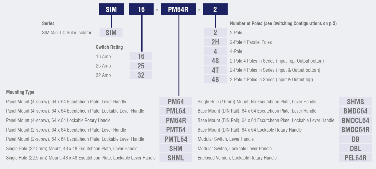
Part Number Configuration

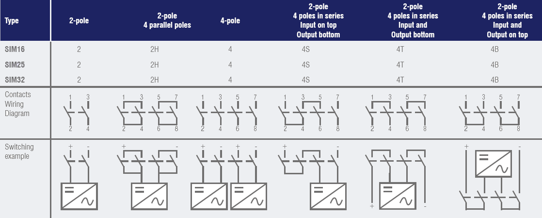
Switching Configurations

Technical Data for DC according to IEC 60947-3


